I recently flashed a pair of Super-Mini ESP32-S3 boards using the online Tasmota flasher here. As I had no need for Bluetooth I went straight for the standard Tasmota (ENGLISH) option – which for anyone who doesn’t know, somehow works automatically for both ESP8266 and some ESP32 boards (ESP32-C2, C3, C6, S2, S3 and ESP8266) which I didn’t know until I took the time to hover over the drop-down option in the Tasmota setup page. Anyway, the “Super-Mini ESP32-S3” boards are widely available and cheap – and they have an on-board WS2812B RGB brightly coloured light.
The job at hand was to make a nice, simple PING sensor with visible display as I’ve been having reliability problems with my broadband which is 5G-based. Well, the 5G supplier, while offering truly unlimited data, when challenged will always come back with “we don’t support routers, you’ll have to test on a phone…” like I’m going to leave my phone hooked up 24-7 to supply broadband for our TV and my testing… yeah, right. Technically these “routers” they refer to are “modems”. I’ve also just discovered that phone USB-C connections are more often than not just USB-2 standard hence unable to transfer full 5G data speeds to another router by USB.
So, back to the modem/routers – I have an “old” 4G LTE modem which has no long-term decent testing facility and a “new” 5g modem which similary has nothing special in testing ability either – you can get both to do a single (well, 4 in a row) PING of, say 8.8.8.8 or 8.8.4.4 (i.e. Google) but then what – I needed to keep an eye on this for some days – or have other family members keep an eye open while watching TV) to prove either way where the problem lies with the broadband. I switched from 5G to the 4G modem but I needed some means to monitor if one was any more reliable than the other.
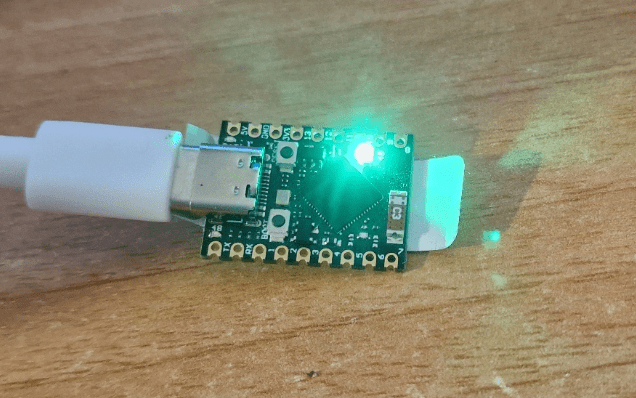
So I initially decided to go with an ESP32 board sitting doing pings regularly and the simplest way, it occurred to me, to provide visual feedback might be to use an RGB LED with GREEN for no failures, YELLOW for some failures (using PING4 – which does 4 pings at a time in quick succession) and RED for no successes in any batch of 4 pings. The Super-Mini ESP32-S3 seemed like a good choice as I had 3 of them sitting around doing nothing and they have that WS2812B LED on the PCB. Mine also have tiny blue and red LEDS, one to the left of the USB-C connector, the other to the right. See the images above.
Of course not all boards will be the same as I found out when grilling my favourite AI for answers. In my case the tiny blue LED flashes at high speed constantly and the tiny red LED just comes on occasionally. Harmless but annoying. So I set about finding out how to stop them completely – it turns out you can’t. The RED light only flashes occasionally as it is attached to the same port bit (GPIO48) as the onboard RGB light and hence comes on when the processor is sending serial data to the WS2812B. And the point of that is? The blue light is apparently somehow attached to the battery mechanism on the board and similarly you can’t program either of them out. By the look of it the only way to hide these is to cover them in tape or if you’re brave enough – remove them with a soldering iron. I don’t recommend the latter unless you’ve a steady hand and a small iron.
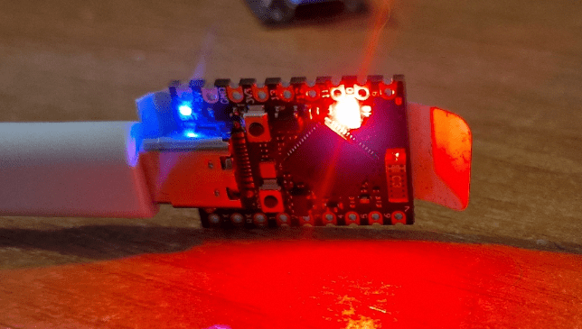
Meanwhile, what’s that damned bright red light doing – the Internet has gone off just as I’m trying to write this blog entry.
It actually took me several attempts to get the image to the left up – I can type on this WordPress blog locally but broadband outages while uploading images just does not work – oh well. Thinking about it, I’ve had problems uploading images to WordPress in the past – quickly resolved by a second attempt, but never understood why they happened until now… short term broadband outage? I’ve never been able to test that until now..
SO, I’m doing a PING every 30 seconds which results in the RGB light changing, to red, yellow or green, and just to make sure the board isn’t STUCK (crashed – unlikely but possible)… I’ve added a brief 1-second flash of WHITE at the 30 second changeover – otherwise the light might stay on green, the board crash and I’d not be informed of an outage. I tried for a 100ms FLASH but tasmota wasn’t having that.
Ok, so my code. In Tasmota you can do lots of things at the console (in the web interface or in the serial console) including setting up GPIOs (I prefer to use the CONFIG section for setting up GPIOs and set GPIO48 to WS2812).
Back to the console… you can create rules and enable them, so here is what I put into the console…
Rule1
  ON System#Boot DO backlog RuleTimer1 10; LED1 #000000 ENDON
  ON Rules#Timer=1 DO
    Backlog
      Ping4 8.8.4.4;
      RuleTimer1 30
    ENDON

Rule2
  ON Ping#8.8.4.4#Success==4 DO backlog led1 #ffffff; delay 1; Led1 #00FF00 ENDON
  ON Ping#8.8.4.4#Success==3 DO backlog led1 #ffffff; delay 1; Led1 #FFFF00 ENDON
  ON Ping#8.8.4.4#Success==2 DO backlog led1 #ffffff; delay 1; Led1 #FF8800 ENDON
  ON Ping#8.8.4.4#Success==1 DO backlog led1 #ffffff; delay 1; Led1 #FF4420 ENDON
  ON Ping#8.8.4.4#Success==0 DO backlog led1 #ffffff; delay 1; Led1 #FF0000 ENDON

rule1 1
rule2 1
The rules go into the console as a single line and if you copy the above, make sure there are no TABS used. Enter rule 1, then rule 2 then enable rule 1 and enable rule 2. This is all non-volatile – after rebooting the board what you should see that the WS2812 will be whatever colour it was before, for a second maybe, then it will go to colour #000000 or nothing.. after 10 seconds, the first rule will run and that will send out a ping and 30 seconds later you’ll see the resulting colour. From thereafter, every 30 seconds the board WS2812B LED will update.
WELL it turns out two things – with care you can reduce the above down to one rule – and secondly, the delay after the full white back to green or red etc, doesn’t work as Tasmota has issues with delay 1. Also I asked the AI for help changing that delay and it came up with ruletimer1 1 (100ms). THAT didn’t work well as it affected the previous use of ruletimer1 (not so smart AI) – so I tried ruletimer2 1 – that didn’t seem to work well, so for a laugh I left out that delay altogether – and that works just fine. Here’s my current version – only one rule, together with the separately entered line to turn the rule on (in case you’ve not already turned on rule 1. Again all of this is non-volatile.
As the rule below stands, every 30 seconds, the device does a ping4 to address 8.8.4.4 and then depending on the result, does a quick flash of white followed by green (or yellow, red etc) until another 30 seconds has gone by.
To see this in action, enter the commands in the Tasmota console (tools – console from the webUI)…. and watch the status.
Rule1
  ON System#Boot DO Backlog RuleTimer1 1; Led1 #000000 ENDON
  ON Rules#Timer=1 DO Backlog Ping4 8.8.4.4; RuleTimer1 30 ENDON
  ON Ping#8.8.4.4#Success==4 DO Backlog Led1 #ffffff; Led1 #00ff00 ENDON
  ON Ping#8.8.4.4#Success==3 DO Backlog Led1 #ffffff; Led1 #FFFF00 ENDON
  ON Ping#8.8.4.4#Success==2 DO Backlog Led1 #ffffff; Led1 #FF8800 ENDON
  ON Ping#8.8.4.4#Success==1 DO Backlog Led1 #ffffff; Led1 #FF4420 ENDON
  ON Ping#8.8.4.4#Success==0 DO Backlog Led1 #ffffff; Led1 #FF0000 ENDON

rule1 1
To monitor the above – in the console you will see a sequence starting at the first line below..
18:08:40.975 RUL: RULES#TIMER=1 performs 'Backlog Ping4 8.8.4.4; RuleTimer1 30'
18:08:41.022 MQT: stat/esp32-pico-d4/RESULT = {"Ping":"Done"}
18:08:41.221 MQT: stat/esp32-pico-d4/RESULT = {"T1":30,"T2":0,"T3":0,"T4":0,"T5":0,"T6":0,"T7":0,"T8":0}
18:08:45.174 MQT: tele/esp32-pico-d4/RESULT = {"Ping":{"8.8.4.4":{"Reachable":true,"IP":"8.8.4.4","Success":4,"Timeout":0,"MinTime":102,"MaxTime":203,"AvgTime":159}}}
18:08:45.180 RUL: PING#8.8.4.4#SUCCESS==4 performs 'Backlog Led1 #ffffff; Led1 #00ff00'
18:08:45.221 MQT: stat/esp32-pico-d4/RESULT = {"Led1":"FFFFFF"}
18:08:45.472 MQT: stat/esp32-pico-d4/RESULT = {"Led1":"00FF00"}
Ignore the line above that says:
18:08:41.221 MQT: stat/esp32-pico-d4/RESULT = {"T1":30,"T2":0,"T3":0,"T4":0,"T5":0,"T6":0,"T7":0,"T8":0}
Broadband testing Day 2
Didn’t take me long to want to get more ambitious just because I could – and so for day 2 I thought I’d simply stick one of those cheap 128*64 SSD1306 displays onto the ESP32-S3. Well, no, because there is an issue (I’m sure there will be a way around it) with the web flashing tool and Tasmota-Display when it comes to the display part. After more time than I care to imagine trying to get an SSD1306 display working on the ESP32 I went to that old standby, the ESP8266. Well, yes and the ESP8266 supports the SSD1306 NO problem – it just doesn’t support PING out of the box. I’ve been putting this off for FAR too long and with a little time to spare, I went off to add PING to a custom tasmota-display build. Painful? Used to be but not any more.
How to make a custom ESP8266 Tasmota with ping:
- Open gitpod using the tasmota master branch: https://gitpod.io/#https://github.com/arendst/Tasmota/tree/master
- Open tasmota/user_config_override.h in the left panel (I’m assuming a PC browser here)
- Add the following line BEFORE the last #ENDIF:
- #define use_ping
- Save the file
- Run this: platformio run -e tasmota-display
A minute or two later you should find (browser refresh) a folder in the left panel called: /Tasmota/build_output/firmware
In there you should find the newly created tasmota-display.bin and a tasmota-display.bin.gz
Grab the latter locally and also go get tasmota-minimal.bin.gz from here… https://ota.tasmota.com/tasmota/release/
In your ESP8266 device which you’ve already set up with Tasmota or Tasmota-display, use the firmware upgrade menu option – use local files option to get the minimal file installed, then once the board has rebooted, your custom tasmota-display file – ensure all is ok and you’re all set to make THIS…
To make use of the SSD 1306 you need a Tasmota console rule we’ll call rule3
Rule3 :H,SSD1306,128,64,1,I2C,3c,*,*,* :S,0,2,1,0,30,20 :I AE D5,80 A8,3F D3,00 40 8D,14 20,00 A1 C8 DA,12 81,9F D9,F1 DB,40 A4 A6 AF :o,AE :O,AF :A,00,10,40,00,00 :i,A6,A7 #
Note that you should NOT enable that rule – it’s not actually a rule, just a convenient way to store infornation in th form of a long string in flash memory. On boot, the display driver reads that string and initialises the hardware.
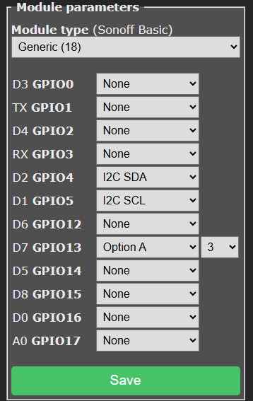
You NEED to set up an unrelated command on for example GPIO13 as well as setting up the SDA and SCL options for the display which also needs 3v3 and ground from the ESP8266 board. See image on the left. Use “Option A 3”, not any variation. Option A is the first option in the module settings once you set the ESP8266 to Generic(18).
Of course there are endless variations on the code below – you don’t have to have it do 4 pings – just ping will do – a single ping – I found every 30 seconds to be a good compromise – you don’t want Google objecting. The PING command supports up to PING8.
On the other hand you want to know about failures as quickly as possible, so I do the 4 pings (PING4) every 30 seconds. For addresses I’ve settled on 8.8.8.8 but quickly checked the others shown below.
Global Providers (Reliable)
- Google DNS:
8.8.8.88.8.4.4
(Google has servers in Spain and Western Europe, so latency is low13.) - Cloudflare:
1.1.1.1
(Very reliable, but sometimes a bit slower than local ISPs in Spain5.) - OpenDNS:
208.67.222.222208.67.220.220
Out of interest, my friendly AI suggested for use in Southern, Spain, for fastest ping times, 178.33.164.29 (OVH Spain) – it wasn’t.
Global Providers (Reliable)
- OVH Madrid:
178.33.164.91(36.27 ms) - XTRA TELECOM Alcobendas:
212.230.255.129(58.9 ms) - Orange Espagne Pozuelo de Alarcón:
89.128.32.234(51.64 ms) - Claranet Barcelona:
80.67.105.163(66.92 ms) - Movistar Madrid:
80.58.61.250(Movistar’s default, reported as 6 ms by a user)
That’s it – standard ESP8266 board, quickly customized Tasmota, small amount of code and you have your own PING tester. I continue to have 5G problems here so I can see this getting use as I build up information to get to the bottom of what’s wrong at my installation. The code below builds on my earlier work – but using the display instead of an RGB LED. The Tasmota site has a full list of commands you can use in brackets (one command per set only, unlike the instructions that the AI gave me). Below is a direct paste from the code I’m using. In the settings above left, don’t ask what “Option A 3” means – no idea ut it is necessary for the display.
Rule1
  ON System#Boot DO Backlog RuleTimer1 1; DisplayText [z][x0][y0]Broadband Tester[x0][y11][h128][x0][y24]Warming up...[x0][y36]Please wait... ENDON
  ON Rules#Timer=1 DO Ping4 8.8.8.8 ENDON
  ON Ping#8.8.8.8#Success==4 DO Backlog DisplayText [z][x0][y0]Broadband Tester[x0][y11][h128][x0][y24]All 4 pings OK[x0][y48][tS][x60]SUCCESS! ENDON
  ON Ping#8.8.8.8#Success==3 DO Backlog DisplayText [z][x0][y0]Broadband Tester[x0][y11][h128][x0][y24]3 out of 4 OK [x0][y48][tS] ENDON
  ON Ping#8.8.8.8#Success==2 DO Backlog DisplayText [z][x0][y0]Broadband Tester[x0][y11][h128][x0][y24]2 out of 4 OK [x0][y48][tS] ENDON
  ON Ping#8.8.8.8#Success==1 DO Backlog DisplayText [z][x0][y0]Broadband Tester[x0][y11][h128][x0][y24]1 out of 4 OK [x0][y48][tS] ENDON
  ON Ping#8.8.8.8#Success==0 DO Backlog DisplayText [z][x0][y0]Broadband Tester[x0][y11][h128][x0][y24]All pings FAILED[x0][y48][tS][x60]Oh DEAR! ENDON
  ON Rules#Timer=1 DO RuleTimer1 30 ENDON
And here’s what the unit looks like (I’ll find a suitable case eventually).
Broadband testing Day 2
Ok, I said I was going to stop…. but this got hold of me and I had to add a little more.. kept my mind off the actual broadband problem for a couple of hours..
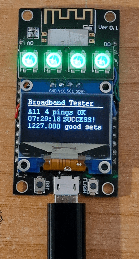
In the process I learned even more about Tasmota and rules. I just happen to have a few 4-LED WS2812B arrays from AliExpress – and I needed something to hold my SSD1306 display level – so to “kill 2 birds with one stone” I glued the LED array to the ESP8266, butted up against the SSD1306. Oh and I finally found a use for that roll of wire-wrap wire I bought years ago – easily hidden connection wires.
WELL I had to use the array for something so I attached it to ground, 3v and GPIO12 while setting GPIO12 to WLED in the Tasmota configuration.
So now I coudl have both the display and the LEDS – but thet’s when I hit the limit of Tasmota rules. I need rule3 for display setup storage and I tried adding WLED commands into RULE1 – the rule simply would not save as I went past the 1500 characters per rule limit. That left rule2 available and the need to split my code between the two. I also decided I needed to display how many good PING sets (30 seconds apart) the board managed without any losses. Good – just add the number of sequential good PING4s and a variable – except that Tasmota at least on the ESP866 insists on using floating point numbers (3 digit precision) and has no TRUC, ROUND or INT commands – hence what you see im the image, right.
Rule1
  ON System#Boot DO Backlog RuleTimer1 1; var1 1; DisplayText [z][x0][y0]Broadband Tester[x0][y11][h112][x0][y16]Warming up...[x0][y28]Please wait...; ENDON
  ON Rules#Timer=1 DO Ping4 8.8.8.8 ENDON
  ON Ping#8.8.8.8#Success==4 DO backlog var1=%var1%+1; DisplayText [z][x0][y0]Broadband Tester[x0][y11][h128][x0][y16]All 4 pings OK[x0][y28][tS][x60]SUCCESS![x0][y40]%var1% good sets; ENDON
  ON Ping#8.8.8.8#Success==3 DO Backlog var1=0; DisplayText [z][x0][y0]Broadband Tester[x0][y11][h128][x0][y16]3 out of 4 OK [x0][y28][tS]; ENDON
  ON Ping#8.8.8.8#Success==2 DO Backlog var1=0; DisplayText [z][x0][y0]Broadband Tester[x0][y11][h128][x0][y16]2 out of 4 OK [x0][y28][tS]; ENDON
  ON Ping#8.8.8.8#Success==1 DO var1=0; Backlog DisplayText [z][x0][y0]Broadband Tester[x0][y11][h128][x0][y16]1 out of 4 OK [x0][y28][tS]; ENDON
  ON Ping#8.8.8.8#Success==0 DO var1=0; Backlog DisplayText [z][x0][y0]Broadband Tester[x0][y11][h128][x0][y16]All pings FAILED[x0][y28][tS][x60]Oh DEAR!; ENDON
  ON Rules#Timer=1 DO RuleTimer1 30 ENDON

rule2
 ON Ping#8.8.8.8#Success==4 DO backlog led1 #001000; led2 #001000; led3 #001000; led4 #001000; ENDON
 ON Ping#8.8.8.8#Success==3 DO backlog led1 #201000; led2 #201000; led3 #202000; led4 #201000; ENDON
 ON Ping#8.8.8.8#Success==2 DO backlog led1 #301000; led2 #301000; led3 #301000; led4 #301000; ENDON
 ON Ping#8.8.8.8#Success==1 DO backlog led1 #300030; led2 #300030; led3 #300030; led4 #300030; ENDON
 ON Ping#8.8.8.8#Success==0 DO backlog led1 #200000; led2 #200000; led3 #200000; led4 #200000; ENDON
Ensure both rules are turned on. The actual light levels on the LEDS are low just because by default they are so bright, it makes the OLED difficult to see. Var1 starts at 1 instead of 0 because of a timing quirk in the rules – cheating but it works. That’s it – I’m done. Reviews to get on with.